Pneumatic knockers (intermittent)
FKL-in series
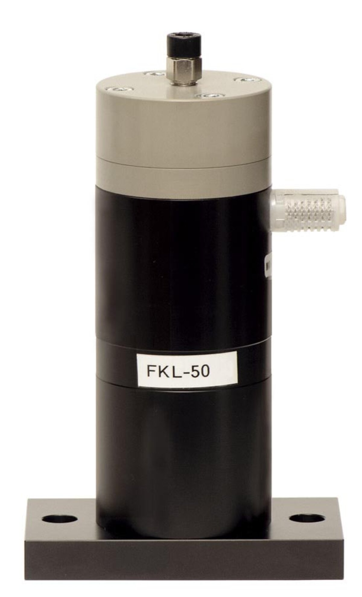
In this further developed pneumatic knocker, a particularly compact design was emphasized. Moreover, the pneumatic knocker is flexible usable – suitable for single-stroke control as well as intermittent self-control.
Impact force:
Using the single-stroke control, the impact force is adjustable steplessly by regulating the inlet pressure.
In the case of intermittent self-control, the user has three levels available to adjust the impact force.
Pulsing:
In cases of using single-stroke control, the impact is triggered by opening and closing an upstream 3/2-way valve (optional). The valve is controlled, for example, by a PLC.
Only an optional automatic self-control (PST FKL -si and/or -in) is required for intermittent self-control. When pressure arrives at the system, the pulsing can be adjusted at the throttle of the PST.
The pneumatic knocker is supplied with a base plate which is used to attach the knocker and transmit the impact impulse. Knocker housing and base plate are made of aluminum. The impact plate (integrated in the base plate) is made of impact-resistant special plastic.
This knocker replaces the previous FKL-…si types.
The pneumatic knocker is designed to operate with dry compressed air (lubrication free). If oil-laden compressed air is selected for the operation of the knocking device, this needs to be kept further on, as the basic lubrication of the knocker will be washed out by the oil-containing air.
In the standard version the knocker can operate in a temperature range of -20 ° to 80 ° C. For temperatures down to -40 ° C or up to 150 ° C, special versions are available - on request.
Performance details:
Type | Min. operating pressure [bar] | Energy / impact [Nm] | Impuls / impact [Ns] | Weight [kg] | Air consumption / impct [l] |
| Control bore | |||||
| -below- -center- -above- | |||||
| FKL-25in | -3,0- -4,5- -6,5- | 1 - 7 | 0,1 - 1,4 | 1,03 | 0,07 - 0,2 |
FKL-50in | -3,0- -4,5- -6,5- | 5 - 21 | 1,2 - 4,7 | 1,85 | 0,1 - 0,3 |
FKL-100in | -4,0- -5,0- -6,5- | 10 - 70 | 2,1 - 14,7 | 4,5 | 0,5 - 1,1 |
| FKL-150in | -5,3- -6,7- -8,0- | 50 - 196 | 10,4 - 40,6 | 9,5 | 1,2 - 2,0 |
| FKL-200in | -5,3- -6,7- -8,0- | 50 - 280 | 28,8 - 80,5 | 14,8 | 2,2 - 3,3 |
* The technical data were measured with a Kistler 3-axis dynamometer. The tests were performed on a massive laboratory test block and displayed with a Kistler Control Monitor (COMO). We reserve the right to improve, modify or withdraw specifications or products without notice or any further obligation.
 Deutsch
 English
 Nederlands

![[Translate to Englisch:] [Translate to Englisch:]](/fileadmin/user_upload/Neue_Bilder_2022/Headerbilder/Header.jpg)


