2. Air pressure sytems
2.1. Air consumption and compressors
The air consumption – especially the average air consumption - of a vibration system forms the basis for a calculation to determine the compressor size
The following table shows the air consumption of our pneumatic vibrators at an operating pressure of 2 and 6 bar in liters per minute.
The values can deviate by 10% due to manufacturing tolerances.
Types | 2 bar | 6 bar | * | Types | 2 bar | 6 bar | * | Types | 2 bar | 6 bar |
K-8 | 83 | 195 | * | R-50 | 100 | 195 | * | DAR-2 | 70 | 200 |
K-10 | 92 | 200 | * | R-65 | 200 | 400 | * | DAR-3 | 100 | 300 |
K-13 | 94 | 225 | * | R-80 | 290 | 570 | * | DAR-4 | 120 | 360 |
K-16 | 122 | 280 | * | R-100 | 370 | 730 | * | DAR-5 | 130 | 390 |
K-20 | 130 | 340 | * | R-120 | 500 | 970 | * | DAR-6 | 170 | 470 |
K-25 | 160 | 425 | * |
|
|
| * | DAR-7 | 180 | 500 |
K-30 | 215 | 570 | * |
|
|
| * |
|
|
|
K-36 | 260 | 675 | * |
|
|
| * |
|
|
|
Types | 2 bar | 6 bar | * | Types | 2 bar | 6 bar | * | Types | 2 bar | 6 bar |
GT-4/6 | 33 | 83 | * | T-50-LP | 70 | 165 | * | FP-12-S | 1 | 25 |
GT-8/10 | 46 | 112 | * | T-50-HP | 80 | 190 | * | FP-12-M | 1 | 20 |
GT-13/16 | 120 | 390 | * | T-65-LP | 90 | 240 | * | FP-12-L | 1 | 20 |
GT-20/25 | 185 | 455 | * | T-65-HP | 110 | 290 | * | FP-18-S | 5 | 57 |
GT-30/36 | 330 | 745 | * | T-80-LP | 150 | 290 | * | FP-18-M | 4 | 25 |
GT-40/48 | 425 | 970 | * | T-80-HP | 150 | 390 | * | FP-18-L | 5 | 46 |
|
|
| * | T-100-HP | 200 | 390 | * | FP-25-S | 13 | 93 |
|
|
|
|
|
|
|
| FP-25-M | 23 | 87 |
|
|
|
|
|
|
|
| FP-25-L | 18 | 93 |
|
|
|
|
|
|
|
| FP-35-S | 23 | 162 |
|
|
|
|
|
|
|
| FP-35-M | 24 | 141 |
|
|
|
|
|
|
|
| FP-35-L | 38 | 135 |
2.1.1 Calculation of the average air consumption
1. air consumption according to table 2. 1.: CONS= ....... Liters/minute
2. operation factor (on/off) × 100 % : OPF = .........%
3. average air consumption = CONS × OPF : ACON = .......... Liters/minute
4. total air consumption = ACON × number of vibrators.
To calculate the average air consumption of different vibrators, the individual average air consumptions should be added together.
To determine the size of the compressor, it is recommended to add 20% of the calculated air consumption as a safety margin. Leaks in the air system as well as other connected devices and future extensions should also be taken into account.
To define the size of the compressor, another factor must be taken into account. It is the highest possible air consumption that occurs when all units are working at the same time and the length of this period.
highest possible air consumption = number of vibrators × CONS for ........... minutes
= .......................... Liters/minute during ........... minutes
Both values, the amount of the highest possible air consumption and the average air consumption, should be taken into account when selecting the compressor.
2.2 Lubrication
Dry or not dry? This is an important question. In general, lubrication helps to increase the service life of moving parts by reducing friction. This also applies to K-series ball vibrators and R-series roller vibrators, as it increases their service life and protects the vibrator from damage caused by frictional heat. Lubrication must always be provided for DAR- series roller vibrators with brass covers and T-series turbine vibrators with unprotected bearings (no lubrication is required for GT types with encapsulated bearings).
Due to special materials and coatings (Teflon), friction can be minimized to such an extent that the piston vibrators of the FP series have very good emergency running properties, but lubrication is absolutely necessary to prevent wear. The FPLF series has a special coating and can be operated without oil in the compressed air.
The question of how many drops of oil per minute are sufficient or how many are too many cannot be answered in general. It is possible that piston compressors release enough oil into the compressed air that an additional lubricator is not necessary. On the other hand, the same type of compressor could release so much machine oil due to leaks, which can lead to a reduction in frequency and force or oil sticking in the DAR vibrator, for example. Air compressors with installed air dryers require an oiler if vibrators are used as described above.
Important for the lubrication of findeva vibrators:
Use oil with viscosity: ISO VG 15 with 15cST/40°C
Klüber Airpress 15 is recommended.
Alternatively, oils with the viscosity: ISO VG 5 with 5cST/40°C can be used.
The oil should not tend to stick. We have listed some types for you here:
Shell Tellus Oil C5
Esso Nuto H5
Mobil Velocite No.4
BP Energol HP 5
for food use: Mobil Whiterex 304 (vegetable base)
Note: Oil with viscosities other than those listed here reduce the frequency and force! The following applies to FP piston vibrators: Distilled water can be used instead of oil. It has a sufficient lubricating effect. Minimum 10 drops per minute.
Check the silencers for traces of oil and adjust the lubricator for minimum (but not total) lubrication. Avoid reducing the performance of piston or roller vibrators by excessive lubrication.
2.3 Air filter and pressure regulator
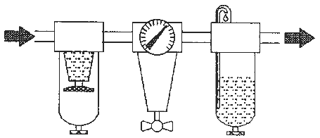
All compressors are fitted with air filters to protect the valves and pistons from wear. This subsequently compressed air is clean enough for all our rotating vibrators. Any remaining small particles are transported through without damaging the vibrator. However, an air filter with a particle passage of 5 mm or less should be used. This helps to extend the service life of the vibrator.
Note: For piston vibrators, the above air filter < 5µm is strongly recommended due to the small tolerance between piston and running surface.

Installation recommendation: Filter, then regulator and lubricator
2.4 Compressed air lines
It is of course possible to regulate vibrators by changing the air pressure or air volume. However, care must be taken to ensure that the air pressure units are correctly dimensioned. If the diameter of the pressure lines is too small, the vibrator will not achieve its full performance.
This applies in particular to the air outlet line. This should be as short as possible, as the volume of escaping (expanded) air is many times greater than the pressure difference.
The corresponding formula is V(in) × P(in) = V(out) × P(out) where P is the absolute pressure and not just the overpressure. This means that a vibrator operating at 6 bar generates an air outlet volume that is 6 × greater than the air inlet volume.

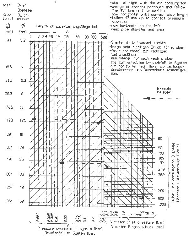
Diagram for determining the diameter and length of the air pressure lines
An air outlet line that is too long or too small prevents the air pressure in the vibrator from being completely converted into vibration energy.
A silencer attached directly to the vibrator is the best way to utilize as much power as possible. To determine the size of the supply line, the diagram above helps to determine the required line diameter.
Example:
- The air consumption is 900 liters per minute at an air pressure of 4 bar.
- The line length is 10 meters.
- Start on the right side with 900 to the left up to the 4 bar line. Now follow this 45° upwards to the vertical dividing line. Continue horizontally to the left up to the 10 meter line. Follow this 45° upwards to the right until you reach the vertical pressure loss line in bar. The required cross-section or diameter can now be read off horizontally on the left.
Note: The air pressure loss in the pipe should not be more than 0.5 bar.
On the other hand, it does not make sense to keep this value as low as possible, as this increases the size and cost of the pipes.
A value between 0.1 and 0.5 bar should be ideal.
The required dimensions of the air outlet pipe can be determined in the same way. Instead of the inlet pressure, use the outlet pressure of the vibrator, which is between 0.2 and 0.5 bar.
2.5 Valves and pressure regulators
2.5.1 Pressure regulator
With the help of pressure regulators (e.g. needle valves), the vibrator can be set to the optimum operating speed. The adjustable flow rate influences the frequency and force of the vibrator.
We recommend installing the regulator between the air filter and lubricator to achieve the best possible results.
2.5.2 Air pressure valves
For some applications, such as emptying hoppers and bins, it is necessary to switch the vibrator on only intermittently. To achieve this, a solenoid valve can be connected downstream of the lubricator. Positioning upstream of the lubricator and regulator is disadvantageous, as the regulator has to be readjusted each time the pressure is built up and the full air pressure is not immediately available. This could cause the vibrator to malfunction. It is also recommended to position the valve as close as possible to the vibrator.
Note: Do not mount air pressure units such as air filters, pressure regulators, oilers, etc. on the vibration system. The air pressure units would not work properly.
CAUTION: Make sure that the inner width of the valve is large enough (refer to the diagram to determine the air hose sizes). Otherwise it is not guaranteed that the vibrator can reach its full power or that the piston vibrators can start up. It is also possible that piston vibrators will not start if the air pressure valve is actuated manually, as the piston vibrator requires a rapid onset of pressure to start up. In the case of manual operation, try to open the valve as quickly as possible or use solenoid valves.
 Deutsch
 English
 Nederlands

![[Translate to Englisch:] [Translate to Englisch:]](/fileadmin/user_upload/Neue_Bilder_2022/Headerbilder/Header.jpg)