7. maintenance and repair
7.1 Maintenance
Under normal circumstances, pneumatic vibrators do not require maintenance if operated carefully.
However, it is recommended that the vibration system be checked for proper operation at regular intervals. The frequency of the system can be checked using a frequency meter. A change in frequency is often the first sign of loss of vibration energy.
Remark: The vibration frequency is strongly dependent on the compressor size and the size of the compressed air tank. For the measurement, it should be noted that the compressed air tank is always filled to the same level.
The normal required maintenance of compressed air units includes:
- Check air filter for contamination or clogging, clean or replace air filter if necessary.
- Check the silencer for contamination or clogging, clean or replace silencer if necessary. FF (Free Flow) silencers (for piston vibrators) can be screwed on and blown free with compressed air.
- Check the oiler, refill oil if necessary.
Remark: Vibrators often fail because the lubricator has run dry and the vibrators in question have not had lubrication. A person should therefore be responsible for checking the lubricator, or a check of the lubricator should take place at defined intervals.
Note (only for piston vibrators which are not lubrication-free): The lubricator can also be filled with distilled water in this type of vibrator. The materials (tread of Teflon-coated aluminum, piston of treated bronze) work excellently oil-free, exclusively with water. However, the water requirement is 5 to 10 times higher than the oil requirement, since water atomizes much more and does not remain as long on the moving parts of the piston vibrator.
7.2 Troubleshooting
7.2.1 The vibrator does not start up
- Piston vibrators only: Remove the piston vibrator from the mounting location, hold it vertically in your hand and switch it on. If the piston vibrator now starts, the start spring in the vibrator should be checked.
- Oil gumming can cause the moving parts in the vibrator to stick (especially in FP and DAR vibrators). In this case, drip ten drops of kerosene into the air inlet to dissolve the stuck oil.
If there is a compressed air jam:
- Remove silencer or exhaust pipe. If the vibrator now starts, check the silencer or exhaust line for blockages and clean or replace.
- Check air pressure supply line at compressor, maintenance unit, end of line.
7.2.2 The vibrator does not always start.
Occurs with piston vibrators, because they need some seconds to reach their start position and therefore start problems can occur with very short pause times.
- Piston vibrators require a few seconds after the compressed air is shut off to allow the spring in the vibrator to set the piston to the start position. A long connecting line between the valve and the vibrator increases the time required even more. A clogged silencer can also be the cause of a longer return stroke of the piston. To check this situation, the piston vibrator should be tested without the silencer and the silencer cleaned or replaced if necessary.
- If a very short pause time (less than 4 seconds) is required, a 2/2 way valve can be used instead of a 2/3 way valve to immediately vent the compressed air line between the valve and the piston vibrator when it is stopped.
- When using manually operated valves, starting problems can occur if the compressed air downstream of the manual valve cannot build up quickly enough. Manual valves must therefore be opened quickly. Electromagnetic or pneumatically actuated valves are, however, recommended.
- Insufficiently large air lines or valves can also cause starting problems.
7.2.3 The vibrator runs too slowly or the force is too low.
With new installation:
- A new vibrator may take up to 15 minutes to reach its full operating characteristics, as grease and anti-corrosion agents must first be pumped out of the vibrator.
- Adjust the pressure regulator to run at higher speeds.
- Check that the air pressure line is connected to the air inlet and not to the outlet.
- Check that the air hose is not kinked.
- Check whether the inner diameter and the length of the air line are not too small or too long (compare chapter 6.1.2.). The same applies to the internal width of the valve.
- Check that not too many compressed air units are running at the same time connected to one air line. The consumers should be connected separately.
For existing installation:
- Remove silencer or exhaust air line. If the vibrator now starts, check the silencer or exhaust air line for blockages and clean with kerosene or replace if necessary.
- Check the air filter for dirt or clogging. Metal compressed air lines can rust and clog the filter.
- Check compressed air supply for leaks, flexible lines for kinks.
- Compressed air oil can gum up in the vibrator. Drip a few drops of kerosene into the inlet of the vibrator.
- Clean dirty vibrators with petroleum as well.
7.2.4. the vibrator has extreme running noises
Noises of high frequency:
- The vibrator runs too fast or is mounted too rigidly. Reduce air pressure and adjust the vibrator to the optimum working frequency.
- The ball of the ball vibrator is worn. Due to the smaller mass of the worn ball, the frequency increases and the force of the vibrator decreases.
cracking noises:
- The attachment of the vibrator is loose.
- If the hopper or hopper is empty, the vibrator should be turned off.
- Turbine vibrators may have damaged bearings.
7.3. repair
All findeva vibrators except the K-series can be easily disassembled, serviced and repaired if necessary.
The following tools are necessary:
- Hook wrench with 4, 5, 6, 7 or 8 mm (see Fig. 7.1.)
- Vise with aluminum jaws
- Hammer
- for T- turbine vibrators: Allen key (2.5 mm: T-50/-65; 3 mm: T-80/-100)
Clamp the vibrator as shown in Fig. 7.2. Do not clamp the side where the end plate is to be opened. Unscrew the end plate in the same direction as the roller or turbine rotates (Fig. 7.3.). Unscrew the caps of piston vibrators counterclockwise.
Annotation: If both end plates are to be unscrewed, first unscrew both end plates before unscrewing them completely so that the housing does not break in the vice.
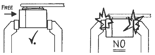
Fig. 7.2 Do not clamp the side to be unscrewed.
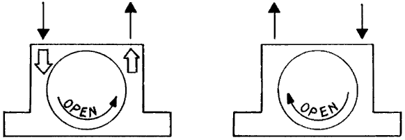
Fig. 7.3. direction in which the end plate is screwed on
Note: When replacing parts, use only original parts. Foreign parts may not be of the same quality and may cause malfunctions.
7.3.1 K-series ball vibrators
Ball vibrators should not be repaired, as only the end plates and the ball can be replaced. If the ball is worn, the raceway, which cannot be replaced, will also be worn. It is only possible to run the vibrator for a few hundred hours with a new ball. The locking plate can be removed by destroying it by drilling holes. The running surface should be checked for damage. New closure plates can be pressed in by hand.
7.3.2 R- Series roller vibrator
When repairing this vibrator, both end plates should be checked for wear caused by the rollers. If grooves are visible this is a sign of insufficient lubrication, both end plates should be replaced, lubrication increased. The end plates are always offered in pairs with left and right hand threads.
The raceway of the roller should be checked for rust and damage. Rust and other impurities cause the roller to run unevenly, resulting in rapid wear of the raceway.
It is possible to run the roller vibrator without silencer plates, but this will significantly increase the volume of the vibrator and dirt may enter the vibrator through the air outlet ducts.
7.3.3 DAR series roller vibrator
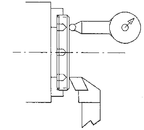
Facing the brass end plate
As with the R-series, the brass end plates can wear out due to insufficient lubrication or contamination. If this is the case, the end plate should be face turned on a lathe (see figure above). This should be done before the end plate has grooves greater than 30 mm (0.03 mm). The remaining plate thickness should not fall below the following values:
The raceway of the roller should be checked for rust and damage. Rust and other contaminants will cause the roller to run erratically, resulting in rapid wear of the raceway.
7.3.4 T- Series Turbine Vibrator
Remark: It should be ensured that the locking screw on the vibrator housing is loosened before moving the end plates to avoid damaging the thread.
The locking screw is 2.5 mm (T-50 and T-65) or 3 mm (T-80 and T-100). Open the end plate counterclockwise. The opposite end plate is the same as the ball vibrators and should not normally be removed.
The turbine rotor and ball bearings can be removed from the housing with the shaft. A ball bearing puller can be used to remove the bearings from the rotor shaft.
When assembling the vibrator, pay attention to the direction of the rotor blades. A hole in the rotor shaft and a corresponding pin on the fixed end plate prevent incorrect installation.
When new bearings are inserted, the vibrator needs a few minutes to reach its normal frequency, as the grease of the bearings still has to spread.
7.3.5 GT-Series Golden Turbine
Normally the GT- Vibrator can be opened only on one side, the turbine can be removed with the bearings and the bearings can be easily pulled off the shaft.
It should be noted that these are special bearings with sealing on one side and special grease equipment. Normal bearings would become dirty and the vibrator would not reach its normal frequency. In case of production interruption, standard bearings can only be used for a short time to bridge a few days until the original bearings are delivered.
When assembling the vibrator, make sure that the turbine is inserted correctly. As shown in Fig. 7.6. the turbine blades must be mounted to the air inlet so that they can be filled, otherwise the turbine would only reach 50% of its speed and power.
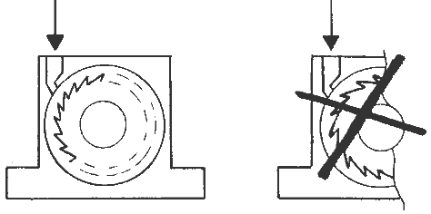
Fig. 7.6 Turbine position
Normally, the GT vibrator is the one with the longest life, since the replacement of the bearings makes it as good as new.
7.3.6. FP- Series Piston Vibrator
It is recommended to open the vibrator at the base plate (the side with the metric mounting hole and the smaller diameter).
The internal spring should now be checked for sufficient length and the piston diameter for its tolerance values (see Fig. 7.7.).
FP type | Ø Piston / Tolerance | Spring length Tolerance |
FP-12-S | 11.985 mm / -20 µm | L=13 mm +/- 3 mm |
FP-18-S | 17.985 mm / -15 µm | L=19 mm +/- 3 mm |
FP-25-S | 24.985 mm / -10 µm | L=26 mm +/- 3 mm |
FP-35-S | 34.985 mm / -5 µm | L=30 mm +/- 3 mm |
Fig. 7.7 Tolerance of piston diameter and spring length
The vibrator will also function outside its tolerance, but the loss area (gap losses) on the piston will increase quadratically. The higher the losses, the less vibration force the piston vibrator can generate, which is particularly noticeable with larger piston vibrators (> FP-25) due to the large piston diameters. Therefore, in order to keep the piston abrasion as low as possible, the lubrication of these vibrators (except FPLF series) is also particularly important.
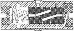
When assembling, make sure that the spring is inserted as shown in Fig. 7.8, i.e. position the smaller side of the spring on the piston, otherwise the vibrator would jam and be damaged.

 Deutsch
 English
 Nederlands

![[Translate to Englisch:] [Translate to Englisch:]](/fileadmin/user_upload/Neue_Bilder_2022/Headerbilder/Header.jpg)