6. installation and operation of the vibrators
6.1 Mounting
Before mounting the vibrator, the mounting location should be checked for its suitability with regard to the best possible work result (compare chapter 3).
The mounting surface should be clean and flat. It should be noted that uneven mounting locations will result in functional errors or breakage of the vibrator. The vibrator should be placed in such a way that its direction of rotation supports the conveying direction as far as possible (compare figure).
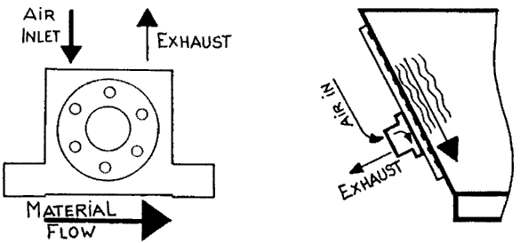
Support of the conveying direction by appropriate positioning
6.1.1 Screws and nuts
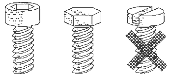
Allen screws / hexagonal screws / slotted screws
The following bolt sizes should be used:
Model | 8/10 | 13/16 | 20/25 | 30/36 | 40/48 | 60/70 |
K-Series | M6 | M8 | M8 | M10 | ---- | ---- |
GT Series | M6 | M8 | M8 | M10 | M16 | M16 |
Model | 50 | 65 | 80 | 100 | 120 | |
R-Series | M6 | M8 | M8 | M10 | M16 | |
T-Series | M6 | M8 | M10 | M12 | ---- | |
Model | 2 | 3 | 4 | 5 | 6 | 7 |
DAR Series | M6 | M8 | M10 | M12 | M16 | M16 |
Model | 12 | 18 | 25 | 35 | ||
FP Series | M8 | M10 | M12 | M12 | ||
It is recommended to use Allen screws or hexagon screws, slotted and cross screws are not suitable. The quality of the SCREWS AND NUTS should be min. 8.8. The screws should be long enough so that at least one turn protrudes from the nut. If the vibrator is to be attached to the object by means of a threaded hole, then it must be ensured that this hole has a thread length which is at least 1.5 times as long as its diameter.
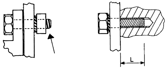
Screw length
CAUTION: Always use fan or spring retaining rings and not domed retaining rings or flat washers. Use of threadlocker (e.g. Loctite 270) is recommended. Observe the handling instructions for the adhesive.

Fan retaining rings / spring retaining rings / domed retaining rings
The retaining rings should be positioned between the mounting plate and the nut or, in the case of FP vibrators, between the mounting plate and the screw.
Please note: FP- Series: The bottom with the mounting hole is the end plate with the smaller diameter. The thread in the opposite base (air outlet) is not metric!
The vibrator should be mounted so that its direction of rotation supports the conveying direction. This can be easily checked by the position of the air inlet (compare Fig. below).
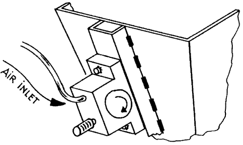
ATTENTION: It is essential that a pneumatic vibrator is securely mounted. It is therefore strongly recommended that the vibrator's attachments be tightened and checked after a few minutes of operation. A loose vibrator can fall off or break off and injure man and machine.
6.1.2 Air connection
An air pressure hose with a sufficiently large internal width is decisive for a good air flow and should therefore be selected according to chapter 2.4. The connection between the main compressed air line and the vibrator should be made by means of the shortest possible flexible line, which should have the internal width specified below:
Profile type | 50 | 65 | 80 | 100 | 120 | 180 |
Inside width (mm) | 8 | 8 | 12 | 16 | 16 | 20 |
All connections to vibrators must be flexible, otherwise they will be damaged by a working vibrator. Additionally fix the air hose to the object and make sure that it is not kinked.
Please note: The threads of the air holes correspond to BSP (British Standard Pipe), but can also be used for G- or R- threads, as well as US NPT (National Pipe Thread), which is conical and has one extra turn per inch. Carefully insert air screw-in grommets and silencers with Teflon tape.
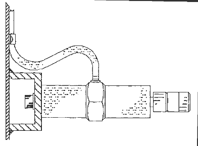
Securing the air pressure hose
Maintenance units, filters, regulators and lubricators should be located as close as possible to the vibrator (less than 2m). If an electromagnetic valve is used to control the vibrator, it should be placed no further than 50 cm from the vibrator. This allows a safe and quick start of the vibrator.
One lubricator for three vibrators is absolutely sufficient. The line lengths from the branch should be the same so that all vibrators are supplied with the same pressure and flow. The same applies to the positioning of several solenoid valves.
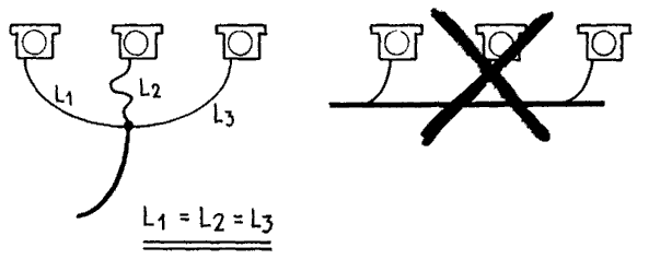
Connection of several vibrators to one compressed air line
When using oilers, an oil of specification ISO VG5 must be used as described in chapter 2.2.
We recommend that a few drops of petroleum be added to the air inlet before initial start-up. This will dissolve the corrosion protection of the new vibrator within the first seconds after start-up.
6.1.3 Silencers
All pneumatic vibrators except R-series can be equipped with silencers at the air outlet. The equipment with the following silencers is suggested:
Vibrator type / model | Silencer | Size | Order number. |
GT-8 /-10, R-50, FP-12 / -18 | Filter Type | 1/8" | 44025 |
K-8 to 25, GT-13 to 25, T-50 to 65, R-65 / -80 | Filter type | 1/4" | 44026 |
K-30 / -36, GT-30 to 48, T-80 to 100, R-100 / -120 | Filter type | 3/8" | 44027 |
DAR-2 | Bronze | 1/8" | 39371 |
DAR-3 / -4 | Bronze | 1/4" | 39372 |
DAR-5 / -6 / -7 | Bronze | 3/8" | 39373 |
FP-25 / 35 | Free Flow | 1/4" | 44029 |
Silencers can become clogged by unclean air. Therefore, the use of air filters is always recommended. However, it is also possible to wash out clogged air filters with kerosene or to unscrew the free flow type and blow it out with compressed air.
Instead of a silencer, an exhaust air line can also be installed. In this case, it must be ensured that the exhaust air line has twice the diameter (inside) as the compressed air line, so that the expanded air can flow out freely without throttling the performance of the vibrator. As described in chapter 2.4. the pressure loss in lines (inlet and outlet) should not exceed 0.5 bar.

Pressure loss
The exhaust line should not be longer than 2 m.
6.1.4 Further
All pneumatic vibrators can be operated outside under the following conditions:
The vibrator is installed so that no liquid can reach it. If the vibrator is exposed to liquids (e.g. rain) one of the following rules should be observed:
The vibrator is mounted so that its air outlet with silencer faces the ground.
If this is not possible, provide the vibrator with an exhaust hose with the help of which the silencer can be fixed pointing downwards so that no moisture or dirt can enter the vibrator.
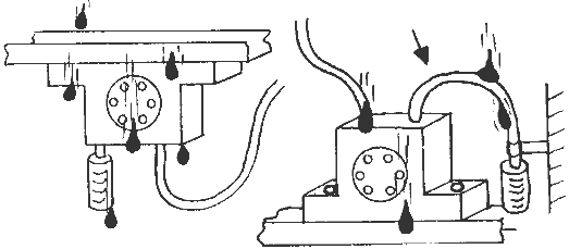
Protection against falling liquids (rain), dirt, etc.
If this is also not possible due to design constraints, the vibrator should be constantly supplied with 0.5 to 1 bar compressed air and equipped with a special flat silencer so that no liquids can penetrate.
CAUTION: Never use a vibrator without a silencer if dirt, dust or liquids can enter the air outlet.
6.2 Operation
After successful installation, the vibrator can be put into operation as follows:
DANGER:
- Wear ear protection around pneumatic vibrators.
- Startup of a vibrator without a muffler should be avoided to minimize the risk of ear damage.
- Make sure that the lubricator (if present) is filled.
- Make sure that the max. possible air pressure on the vibrator does not exceed 7 bar.
- Check that all fasteners are tight.
- Make sure that the air pressure connection is also attached to the air inlet.
- Vibrators mounted on bunkers, hoppers or similar should not be switched on when they are not filled to avoid damage to the structure.
After the first start-up, the vibrator reaches its normal frequency and force after a few minutes, because the moving parts of the vibrator are protected with anti-corrosion greases and these are still solid due to the low temperature.
- It is recommended to turn on the vibrator periodically for the following reasons:
- The lifetime of the vibrator is increased. Compressed air energy is saved.
- Vibration energy is only used when the material can flow freely, thus preventing the material from compacting when locks and outlets are closed.
- For many applications the following working interval has proven to be efficient: On time 10 to 30 sec, pause time: 1 to 5 min.
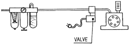
Periodic control
For periodic operation, electromagnetic valves with timers or machine controls are particularly suitable. The valve should be placed between the maintenance unit and the vibrator. The closer the valve is positioned to the vibrator, the better the immediate start and stop is guaranteed. If the valve is positioned far away from the vibrator, the air pressure line must first be vented or filled after the switching operations until the vibrator reaches its desired operating state (ON/OFF).
It is often not necessary to operate the air vibrator at full power (e.g. 6 bar). To do this, use a pressure regulator to find the natural frequency of the system/material. This saves costs and extends the service life. With FP- vibrators this can also be done with the help of the FF- (Free Flow) silencer.
CAUTION: It is essential to wear hearing protection for the following test.
If an exhaust air line is connected, the frequency and force of the vibrator without and with the exhaust air line connected should be measured during commissioning. Differences in these measured values indicate a loss of energy through the exhaust air line. If the loss is too high, it can be reduced by using a shorter exhaust line. The same procedure can be carried out with the silencer insert to check whether it has sufficient flow or is clogged.
If the vibrator does not start or does not reach its operating capacity, compare chapter 7.2.1 (Troubleshooting).
 Deutsch
 English
 Nederlands

![[Translate to Englisch:] [Translate to Englisch:]](/fileadmin/user_upload/Neue_Bilder_2022/Headerbilder/Header.jpg)